Persistence Rudder Bearing Replacement
When we purchased Persistence we were told that the rudder bearing would need to be replaced over the next few years. There was not a lot of play so we decided to leave it as is and monitor. In 2020 we noted that there was now more play when sailing in quartering seas most notably. This will document the process.
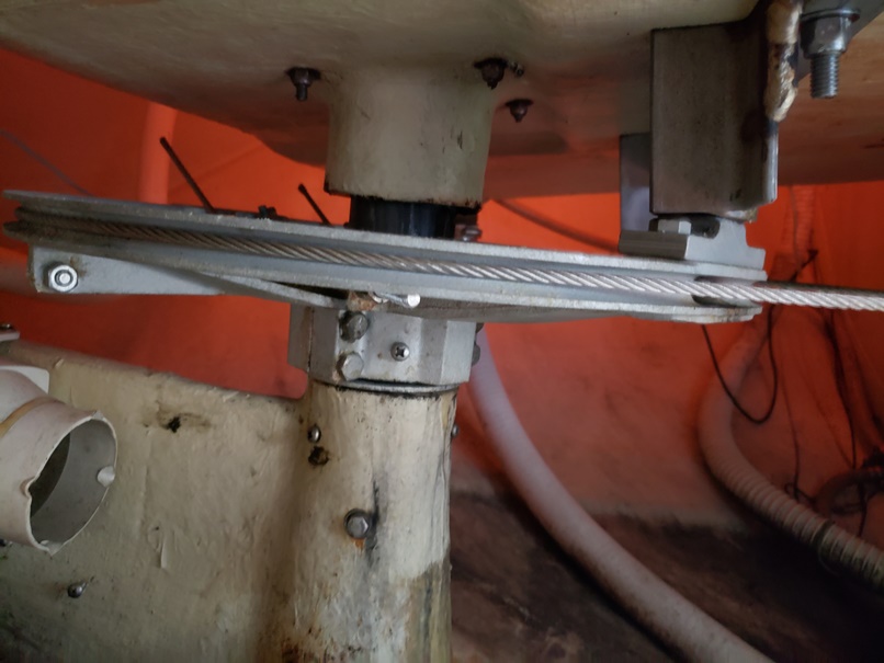
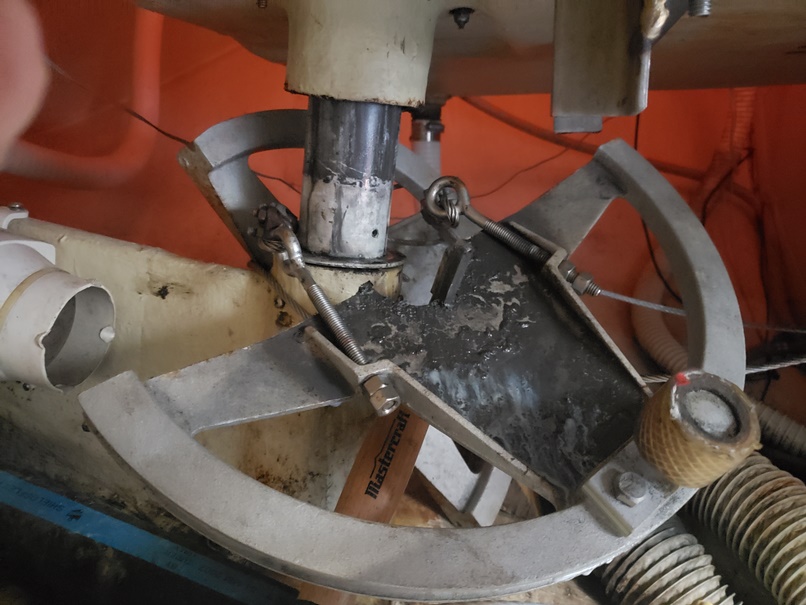
Steering assembly at first look. Rudder quadrant with steering cables fully tensioned
The first step was to clear out the lazarette and crawl inside for a look. In the pictures above and below we are looking at the quadrant and get an idea of what needs to be done. There are two long bolts that tension the steering cables which need to be eased and then 6 bolts that hold the two halves of the quadrant together.
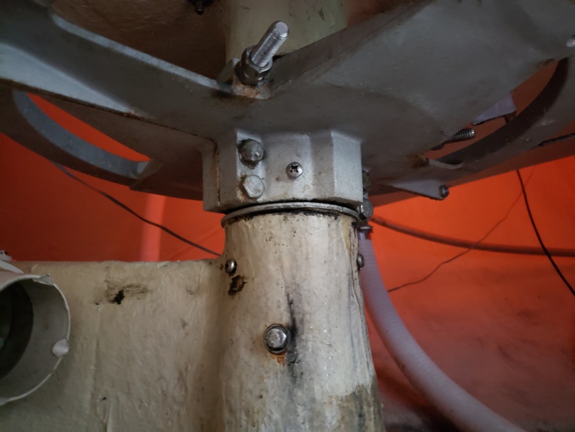
A better look at the cable tensioning bolt
The cable tensioning bolts have 9/16 inch nuts. The two nuts were backed off so that the steering cables were slack. Once this was done the four main bolts (Also 9/16") that hold the quadrant together at the rudder post were removed. You will notice in above photo there are also two small bolts one at each side on the outer ring of the quadrant that also need to be removed.
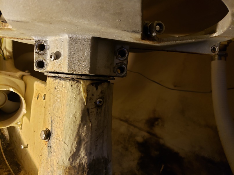
Bolts removed and cable tension eased
With the bolts removed the two halves of the quadrant were separated. The back half easily came off. The forward half is much more firmly attached.
Next steps will be to block the rudder to take weight off the quadrant and the pin on the top of the rudder post. Hopefully with the weight off the forward half of the qudrant can be removed, followed by the pin on the top of the rudder post in the cockpit and then the rudder can be lowered out of the boat. We will see how well that works out.
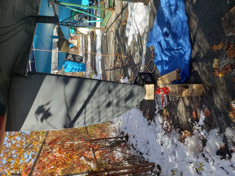
Rudder lifted 1/4 inch with blocks and jack
Before removing quadrant the rudder was lifted about 1/4 inch to take any weight off the quadrant. Then it was "how do I get the quadrant off?" time. We were lucky in that all the bolts came out without any difficulty and the aft half of quadrant came off easily. Using rubber mallet, framing hammer and a block of wood we attempted to remove the forward quadrant half with no luck. Penetrating oil was applied and a day later tried again. This time we tapped the quadrant from the top on the outer edge with flat side of hammer and it moved! Unfortunately it was still stuck to the post. In the pictures above you will see a screw head on the collar of forward quadrant. This was in fact screwed into the rudder post and once removed the quadrant came off easily. Fortunately the key stock came off with the quadrant so we were spared the headache of trying to unfreeze that. In the photo below you can see the key stock still attached to the quadrant.
Both halves of quadrant removed
With the work inside the boat complete it was now time to remove the pin on the top of the rudder post. Unfortunately it snowed the day before (on November 3rd!) so it was a bit ugly. The wheel was removed for easier access to the pin and for bearing access later. Then the pin easily came out as well.
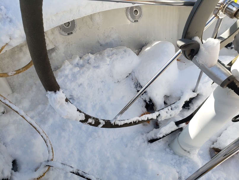
Snow. Ugh. Where is the rudder post in this mess?
Oh. Here is the pin
Pin removal at top of rudder post
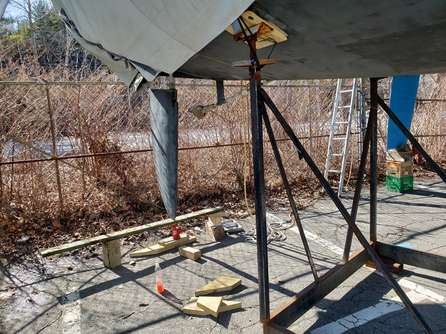
Finally ready to drop the rudder. Manually held it up and kicked out the jack and then each block while lowering between each step. There were no issues with this process. Next step is to take the rudder home for the winter.
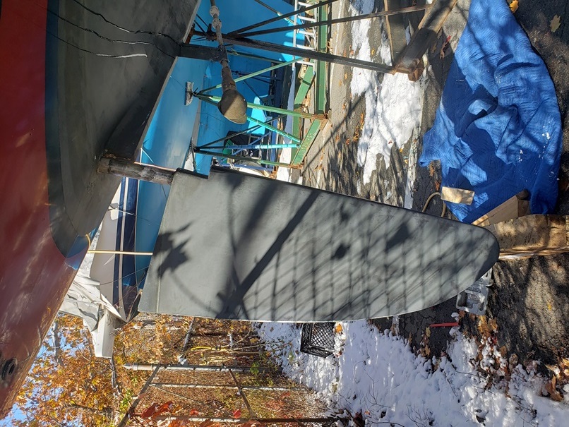
Lowering rudder
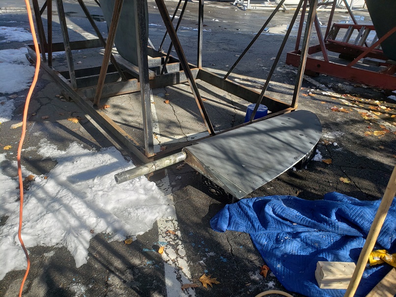
Rudder removed.
One of the bigger concerns with this job was whether there would be sufficient clearance under the hull to remove the rudder. From measurements inside the boat we had decided we needed 22 inches. With the boat on the cradle there was in fact 22.5 inches available (Note that the bottom of keel when sitting on cradle is 12 inches off the ground). When the rudder was lowered there were just over 2 inches to spare so all that is needed is just over 20 inches.
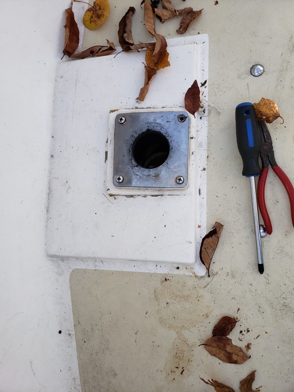
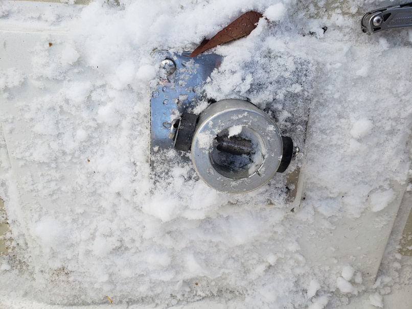
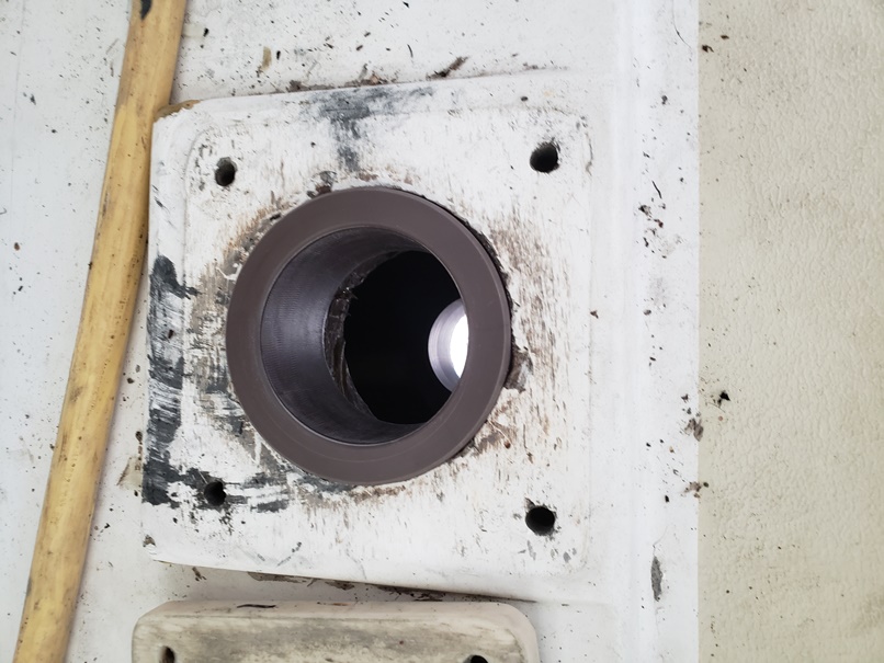
Cover plate in cockpit
The next step was removal of the bearings. Unfortunately I was not exactly sure where thse were located other than in the tube. I suspected and was told by Rod that there was one where the rudder post site in the cockpit floor under the metal plate and a second where the rudder exists the hull. Rod had told me his lower bearing slid out when he dropped his rudder on Equinox.
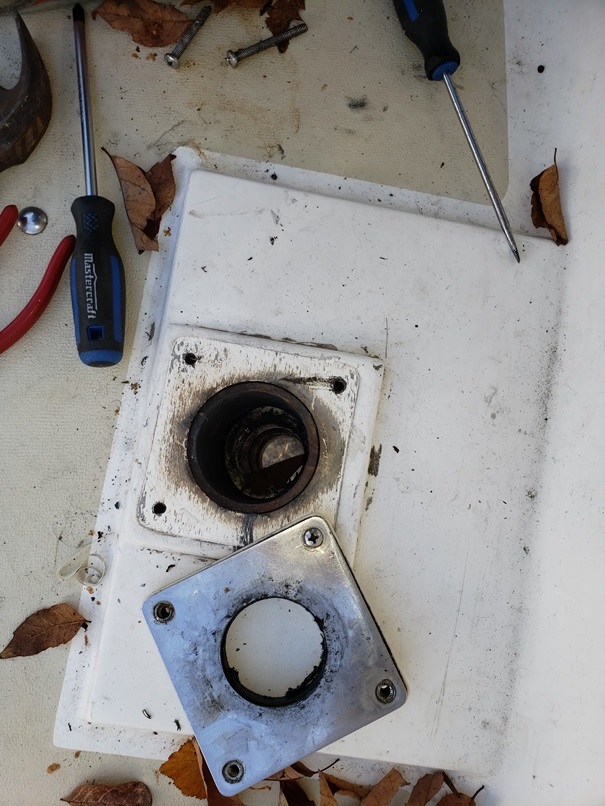
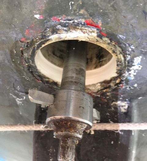
Upper bearing? Clearly visible but not easily removed.
The first step was to remove the
metal cover plate in the cockpit. It turned out that this was not screwed
in place but was through bolted. This resulted in more quality time inside
the cockpit locker to remove the nuts. With the plate removed we could see
the "upper bearing". Quotation marks are used for a
reason. This bearing is not made of a material like Delrin as the other
bearing(s) are. It seems to be a resin of some sort - likely just
fibreglass. No amount of pushing, no amount of banging with a hammer and
tube and no amount of any other technique would budge this bearing. We
could wedge a flat head screwdriver in between the bearing and tube but this
would not loosen it. At a standstill now it was time to go home for the
day and return with some more aggressive tools.
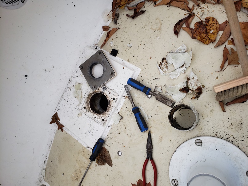
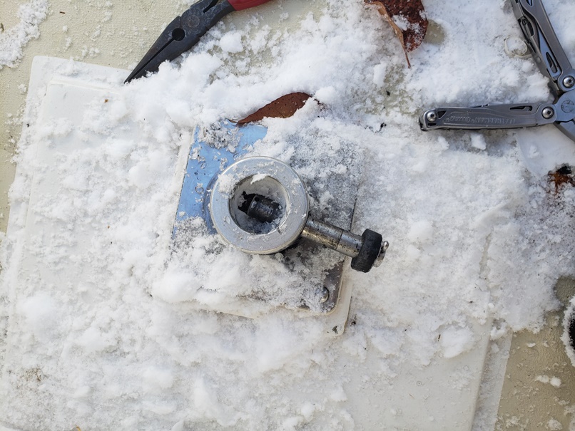
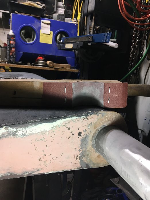
Upper bearing out. The tools in this picture tell the story.
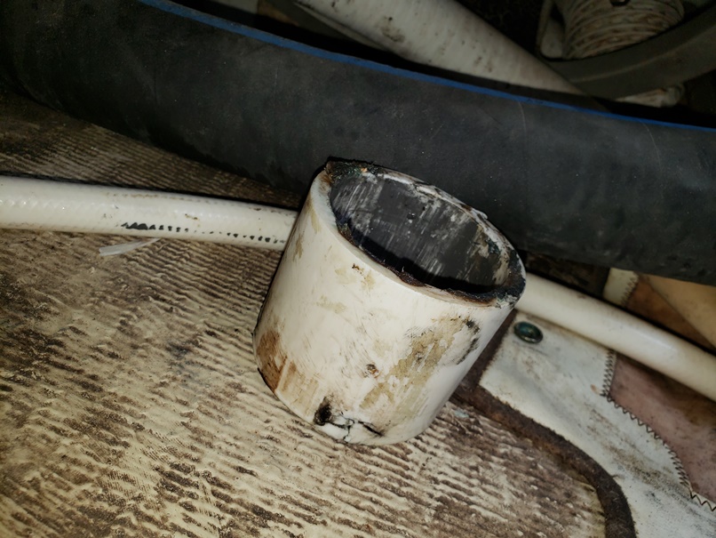
Finally the bearing was out. This "bearing" seems to be made of some laminated resin such as fibreglass. It was adhered to the rudder tube with something permanent as well. To remove a drywall saw was used to cut a seam in the bearing and then a wood chisel wedged in place starting at the cut and working around the entire outer edge of the bearing. Once parts were freed from the rudder tube they were unceremoniously pulled free with pliers. This upper bearing essentially came out in pieces. The good news is that the inside of the tube cleaned up well and a length of 3.5 " ABS pipe was a very snug fit in the hole demonstrating that a new bearing will also be snug.
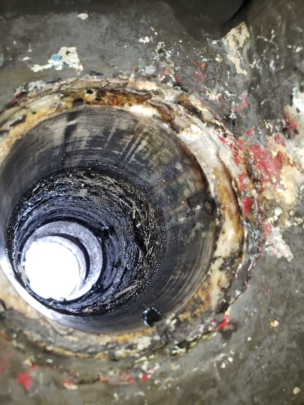
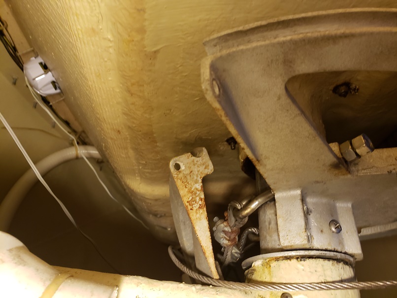
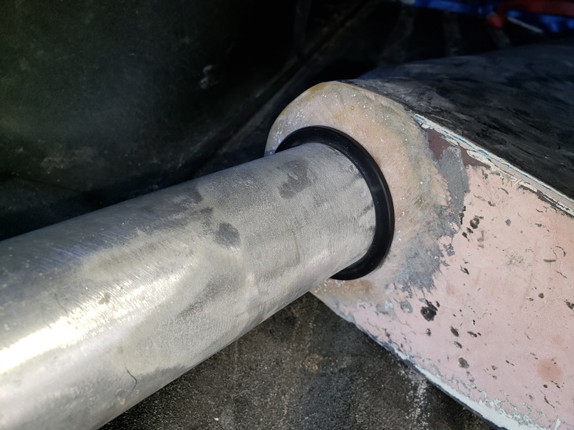
View from beneath the hull. The lower bearing is visible, then about 4 inches of packed grease and the "middle" bearing above.
It was now time to work from below. Looking up the rudder tube from beneath the hull there is a bearing at the bottom of the tube, then a lot of grease and then a second bearing in the rudder tube just beneath where the quadrant would attach to the rudder. On top of the lower tube inside the boat there is a aluminum washer sitting atop the middle bearing and rudder tube. Above there is a picture that is captioned "both halves of the quadrant removed". In that photo you can see the aluminum washer. That washer was in fact attached to the bearing. I wedged it off before removing the middle bearing. It was nailed to that bearing so I suspect the bearing comes with the washer attached to it. Note that there were also two screws thru the rudder tube holding the middle bearing in place that had to be removed. You can see the two screws and a bolt for greasing the rudder tube in the photo above with the caption "bolts removed and cable tension eased".
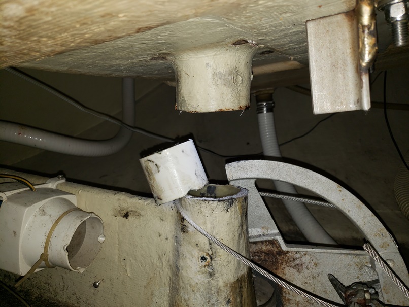
Middle bearing popped out
From below the boat we used a length of hardwood to rest against the lower rim of the middle bearing and then tapped that wood with a hammer (a big one) repeatedly to push the bearing out. This bearing actually came out easily! This left just the lower bearing to remove. Unfortunately no amount of hammering would move the lower bearing. Reading notes by Art Kelly and Don Battaro make us believe this bearing may be epoxied in place. The decision was made to leave this bearing for now and measure the actual tolerances before deciding what next steps to take. Our friend with a machine shop is currently away so we will look at this in a month when someone with much more experience can advise on next steps.
Middle bearing. Appears to be some material similar to delrin.
Our friend Phil is back and the rudder work has picked up. Phil has a machine shop in his house and will be working on the rudder there. He is cleaning up the rudder stock (post) and machining and installing the new bushings. The first problem encountered was pitting in the rudder stock just above where it enters the rudder. The stock is solid aluminum and still strong but this needed to be addressed. Problem number 2 is that after 30 years of wear the stock is no longer perfectly round at the lower bushing and is slightly smaller diameter than when new.
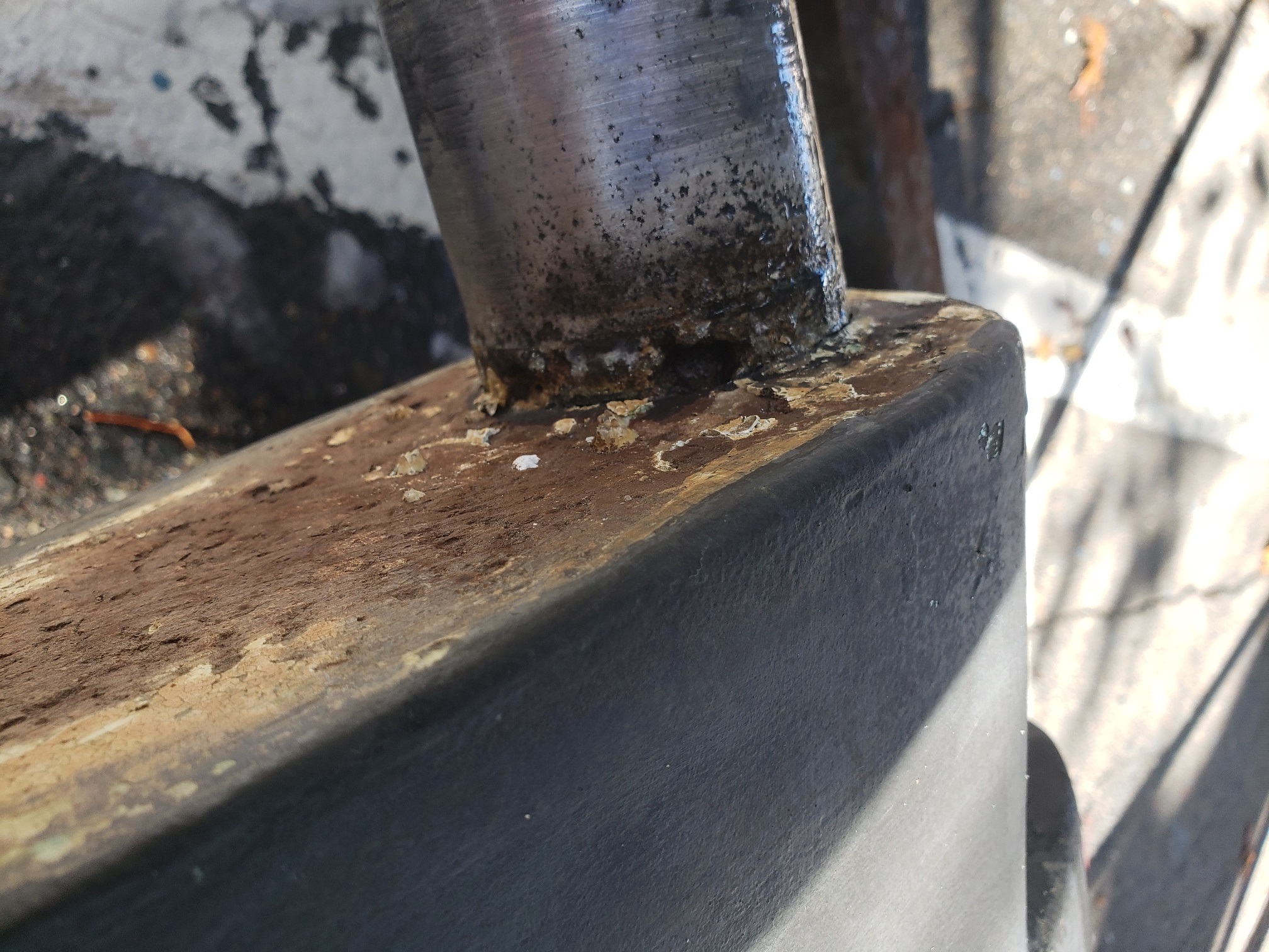
Pitting visible on rudder post just above rudder
When the rudder was inspected by Phil he announced that it could be repaired and would be as strong as ever. First step was to remove some rudder material where the post enters the rudder and then clean up the area. Step 2 was to take the rudder to have the aluminum post welded to fill the pitted areas. Step 3 was to build up the rudder post at lower bushing to proper dimensions and tolerances. For this a product called Belzona 1121 is used to build up the shaft outer diameter and then it is next machined to its factory specifications.
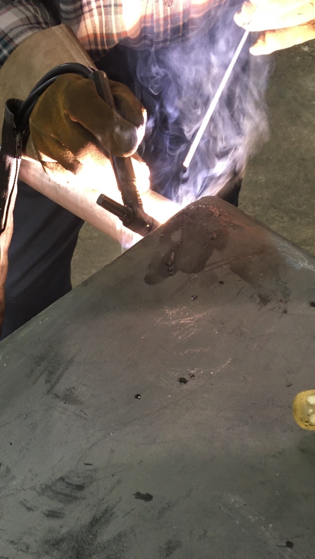
Welding the pitted areas was a challenge
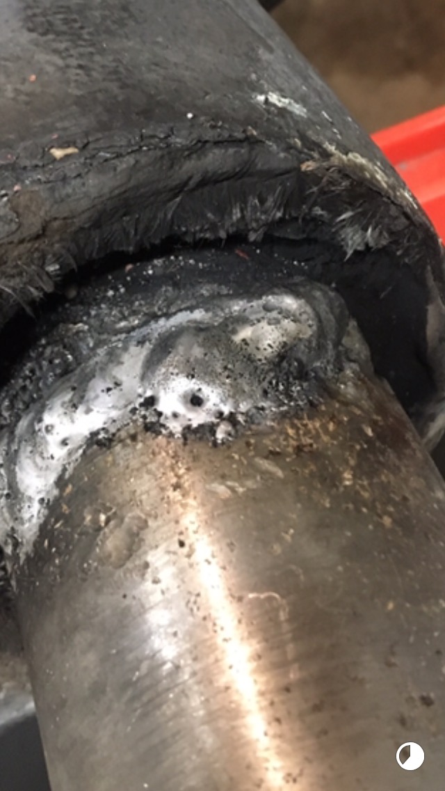
Welding complete. Time for cleanup.
Cleanup process is complete and in process of final machining of shaft to be within tolerances
Repairs to rudder shaft complete. Outer diameter now factor spec once again.
Lower Bearing Update
The lower bearing on Persistence resisted all efforts to remove using pullers and other standard methods. In the end it was required to cut it out. It should be noted that on the 1990 model Frers 33 Equinox it came out easily so it must be inferred that either Persistence was different or later models used a different method of construction. A precision cutting tool was crafted that consisted of two spacers with the outer diameter matching that of the rudder tube and a long bolt that carried through both spacers with a cutting blade attached. It took two hours using this tool to cut out the lower bushing.
Bushing cutting tool
The weather is changing with early hints of warmer Spring days to come. It is time to think about putting the rudder back in place. The lower and middle bushings were previously installed by Phil and he left an upper bushing for cockpit sole area to be installed later. Below are pictures of the new top bushing and the reconditioned plate that covers it.
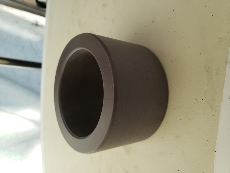
New upper bushing
Upper bushing test fitted
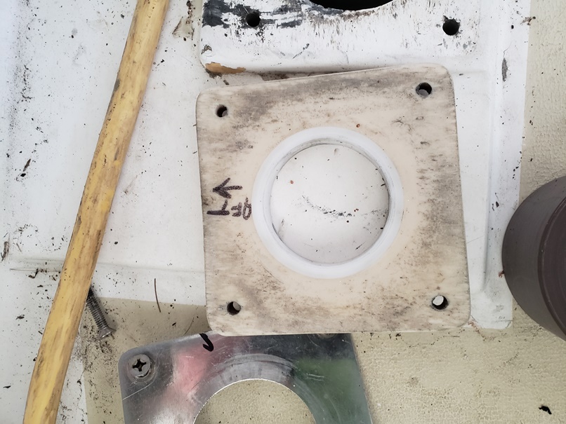
Top plate now also has a bushing
Project has been completed! Rudder and steering now back in place. The reinstallation was relatively simple but a few thoughts that may be of use:
1. Before re-inserting rudder make sure that the quadrants and cables are on the proper sides of the rudder tube. If this is not the case and rudder is re-inserted you will have to undo one of the cables from the front quadrant or drop the rudder again.
2. Lots of pictures and be sure to study them. Prior to starting the project I took a number of photos. I should have taken more! It is much easier to get a camera or phone into a suitable position to take a photo than to position your head! Also is easier to study them afterwards. These pictures are very useful when putting things back together or for planning to take them apart. Look for screws and bolts!
3. Look for screws and bolts! Persistence had one screw attaching the forward half of rudder quadrant to rudder post, three screws holding in the upper bushing (the one inside cockpit locker) and 4 that we never saw holding in the bottom bushing. Something held in the spacer bushing at cockpit sole level but not sure what. Detailed pictures would have shown these and saved many hours spent trying to free lower bushing and eventually cutting it out. Also would have saved much time removing the quadrant.
4. When putting rudder back in place it will be tighter fit than when it came out. Twist the rudder back and forth as pushing into place. Also remember that it is not 90 degrees to ground level. We used a hydraulic jack, levers and three people.
Rudder being re-inserted using lever, jack, dish soap and persistence!